Vt Commodore Ignition Wiring Diagram, Complete Wiring Diagrams For Holden Commodore VT, VX, VY, VZ, VE, VF, 5.36 MB, 03:54, 32,796, John Amahle, 2018-08-01T19:37:41.000000Z, 19, Vt Commodore Ignition Wiring Diagram, to-ja-to-ty-to-my-to-nasz-swiat.blogspot.com, 1272 x 1800, jpeg, bcm pcm 12j swiat nasz, 20, vt-commodore-ignition-wiring-diagram, Anime Arts
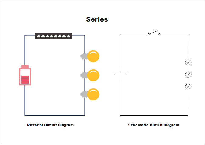
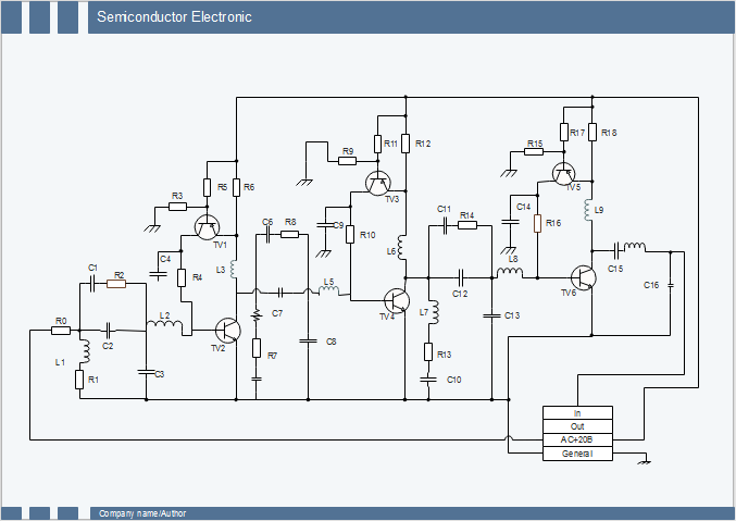
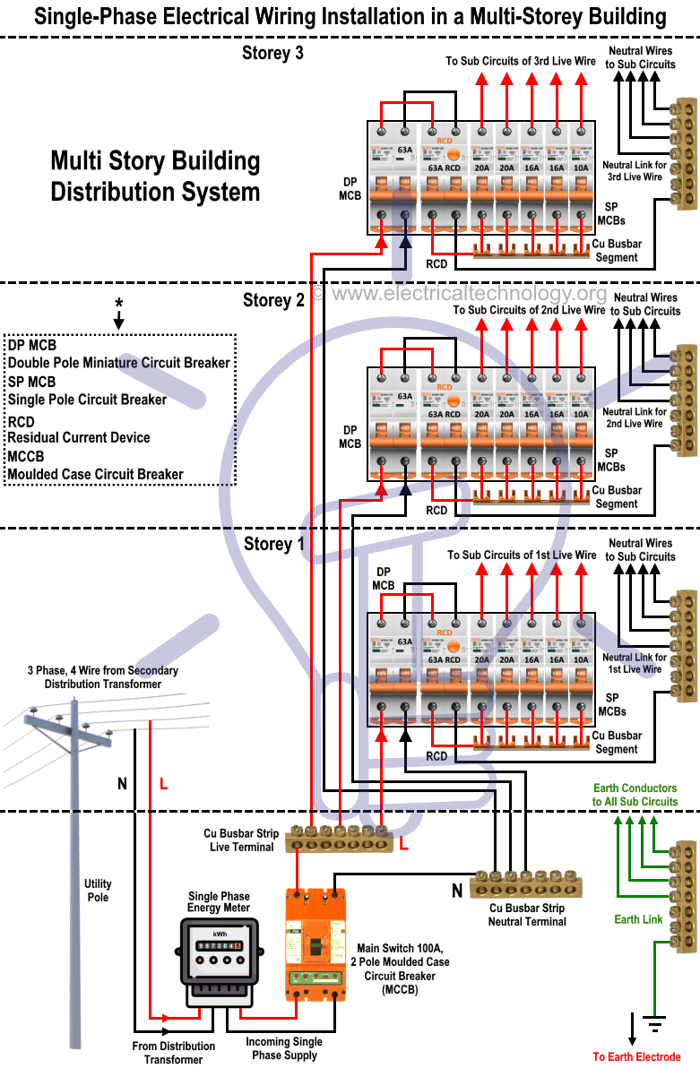
Wiring diagram is mainly used to know how connections are actually made. A wiring diagram is sometimes helpful to illustrate how a schematic can be realized in a prototype or production environment. Circuit diagram or schematic diagram not classified into single line or multiline diagram. As a adjective schematic is represented simply.
The components of the system are displayed as simple shapes or diagrams. The main difference between a wiring diagram and a block diagram is that wiring diagrams are mainly used in electrical applications. Wiring diagrams, or layouts, illustrate the physical connections, or wiring, between components. They are crucial to the assembly of the circuit or system. Typical ac wiring diagram wiringdiagramall. blogspot. com. Electrical schematics 101 www. chanish. org. Wiring diagram boat electrical panel fuse diagrams switch 12v bass basic volt marine schematic tracker dummies ac schematics 1993 pontoon. Difference between single phase & three phase induction motor in 2020. Ladder diagrams show how a circuit works logically and electrically.
What is the difference between schematic diagram and wiring diagram for electrical connections
What is the difference between schematic diagram and wiring diagram for electrical connections
Difference Between Schematic Diagram And Pcb Layout - Points To Note Relating To Pcb Layout

What is the difference between schematic diagram and wiring diagram for electrical connections
The Similarities And Differences Between Series Parallel Circuits - Wiring View and Schematics
Difference Between Schematic Diagram And Wiring Diagram

Difference between Schematics and Circuit Diagrams

Easily Learn the Key Difference between Schematics and Circuit Diagrams | Design World

3 Phase To Single Phase Wiring Diagram - Cadician's Blog

Difference Between Pictorial and Schematic Diagrams | Lucidchart Blog
