Vt Commodore Ignition Wiring Diagram, Complete Wiring Diagrams For Holden Commodore VT, VX, VY, VZ, VE, VF, 5.36 MB, 03:54, 32,796, John Amahle, 2018-08-01T19:37:41.000000Z, 19, Vt Commodore Ignition Wiring Diagram, to-ja-to-ty-to-my-to-nasz-swiat.blogspot.com, 1272 x 1800, jpeg, bcm pcm 12j swiat nasz, 20, vt-commodore-ignition-wiring-diagram, Anime Arts
Wiring cover magnet spacer end block (with screw holes) front side of lock c. Rotate magnet, end blocks and wiring cover as shown, then reassemble. Rotate board 180°, then reassemble. End block (with screw holes) magnet end block wiring cover spacer board front side of lock a.
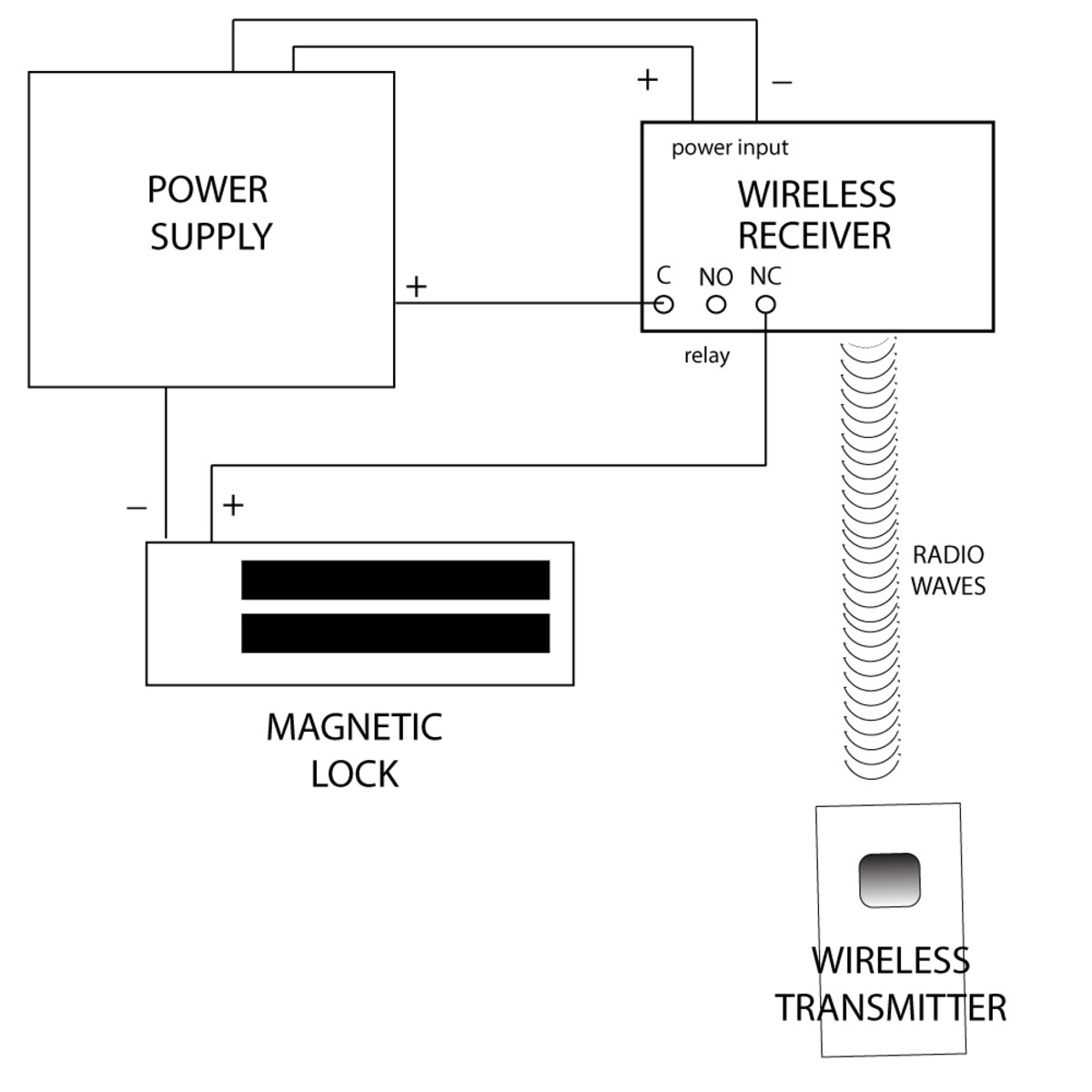
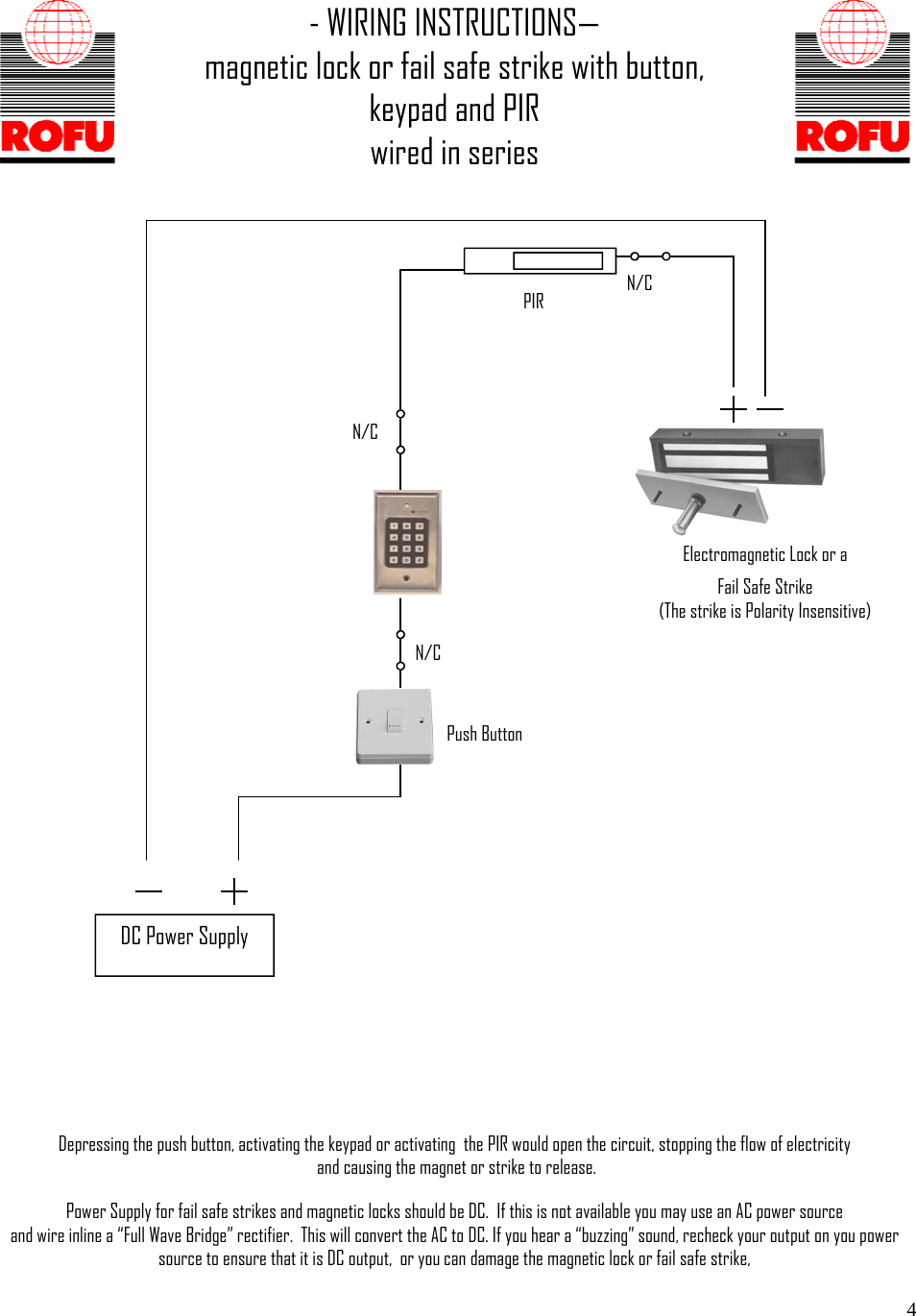
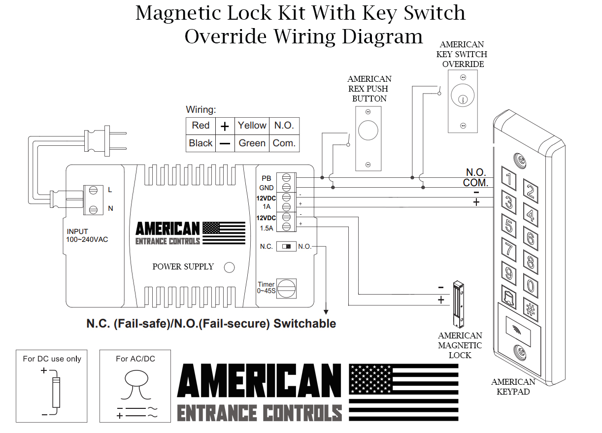
Electromagnetic lock or a fail safe strike (the strike is polarity insensitive) push button. Power input power supply trigger spdt r elay 3a@12vdc status led: No power coil sensor input timeradjust shorten 12vdc 24vdc voltage selection jumpers check jumper settings before connecting the lock to 24 vdc input power. Damage to the lock may result from incorrect. Select jumper position for 12vdc or 24vdc. Connect power to magnetic lock. When all is operating properly, tighten all screws as shown. Wiring the electromagnetic locking system in the simple diagram above, you can see that the electricity travels in an unbroken loop. Em lock system wiring diagram.
Electromagnetic Lock Wiring Diagram - Wiring Diagram & Schemas

Em Lock Wiring Diagram | Wiring Library

External Mag Lock Wiring Diagram / Em Lock Wiring Diagram | Wiring Library - The range includes

31 Magnetic Door Lock Wiring Diagram - Free Wiring Diagram Source

31 Magnetic Door Lock Wiring Diagram - Free Wiring Diagram Source
Electromagnetic Lock Wiring Diagram - Wiring Diagram & Schemas

External Mag Lock Wiring Diagram / Sdc 1511snakv Delayed Egress Magnetic Lock 1650lbs

Tech Tips: Electromagnetic Lock Release Requirements
Best Magnetic Door Lock Wiring Diagram Pdf Most Popular - Switch

Wiring Diagram For Maglock
